1.Overview
The Balisong shaped device is designed to be a performance prop, it belongs to the same functional category as LED poi, glow staffs, and glow gloves, and is manipulated visually for performance purposes. It is not a knife. It was manufactured blunt, and the cast epoxy tip is brittle and not designed to hold an edge.
2.X-ray signature
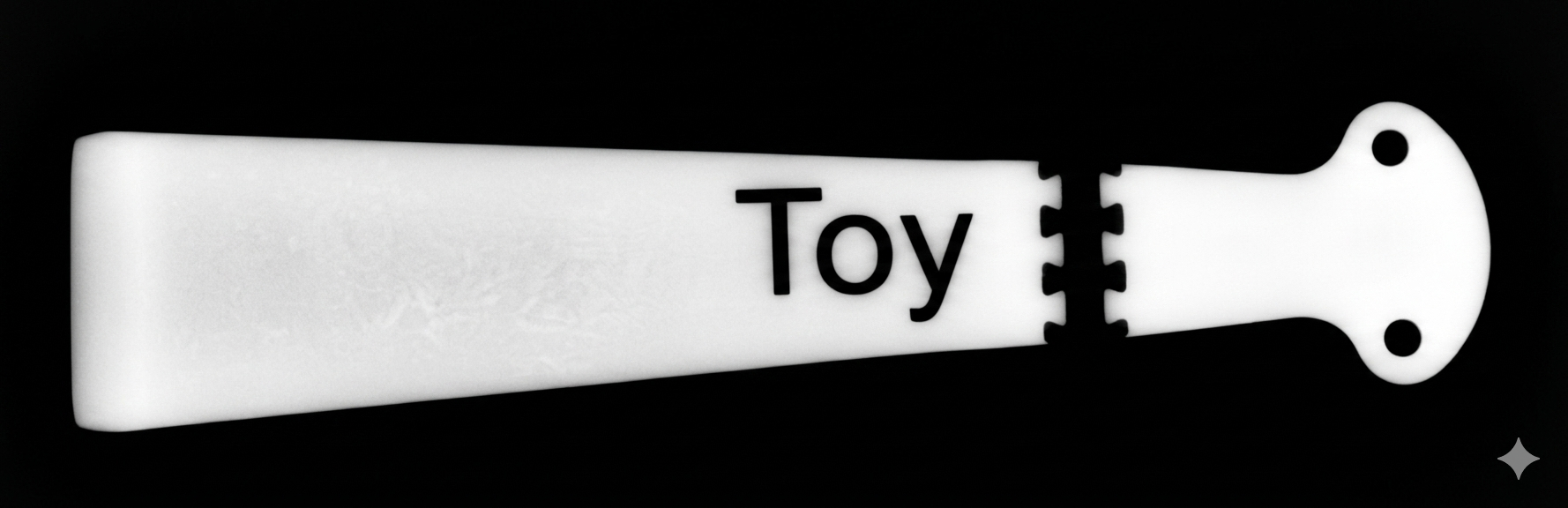
The unit is designed to present a clearly disconnected profile on X-ray equipment. The tip is cast tungsten loaded epoxy and appears dark on a scan. Between the tip and the handle pivot points there is a short plastic segmentation link, fabricated in PLA. PLA is light and this link is designed to produce a visible break in the outline of the unit when scanned. The word TOY is also molded into this segment in PLA, further identifying the unit as a performance prop rather than a weapon.
Together these features produce a scan signature that is discontinuous rather than the uninterrupted profile a functional knife would produce.
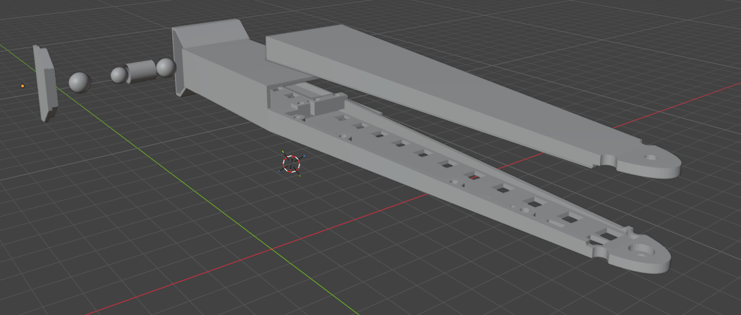
3.Tip and segmentation link
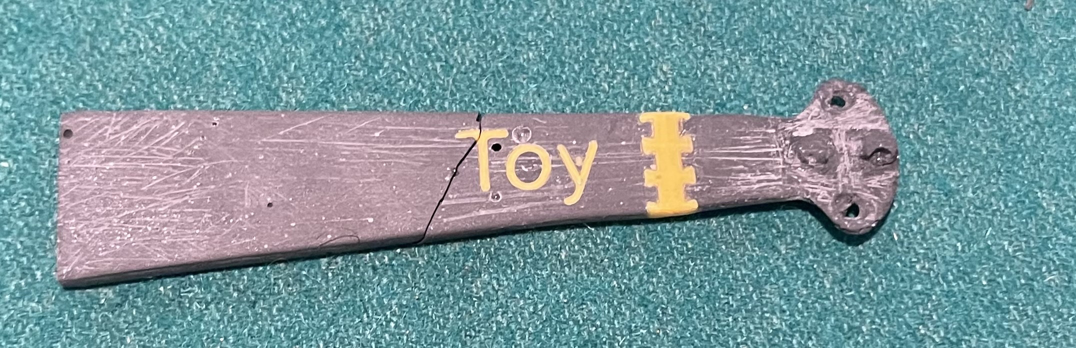
The tip is cast tungsten loaded epoxy formed around two brass pivot pins. It contains no ferrous metal and is not magnetic. It was manufactured blunt, and the cast epoxy is brittle, so the tip is not designed to hold an edge. Under lateral impact the material fractures rather than deforming.
Connecting the tip to the handle pivot points is a short segmentation link fabricated from PLA plastic in three dovetail interlocked sections. The word TOY is molded into this link in a contrasting polymer. Both the segmentation and the TOY lettering are present specifically to break up the silhouette of the unit on an X-ray and to make its classification as a performance prop unambiguous.
4.Handle assembly
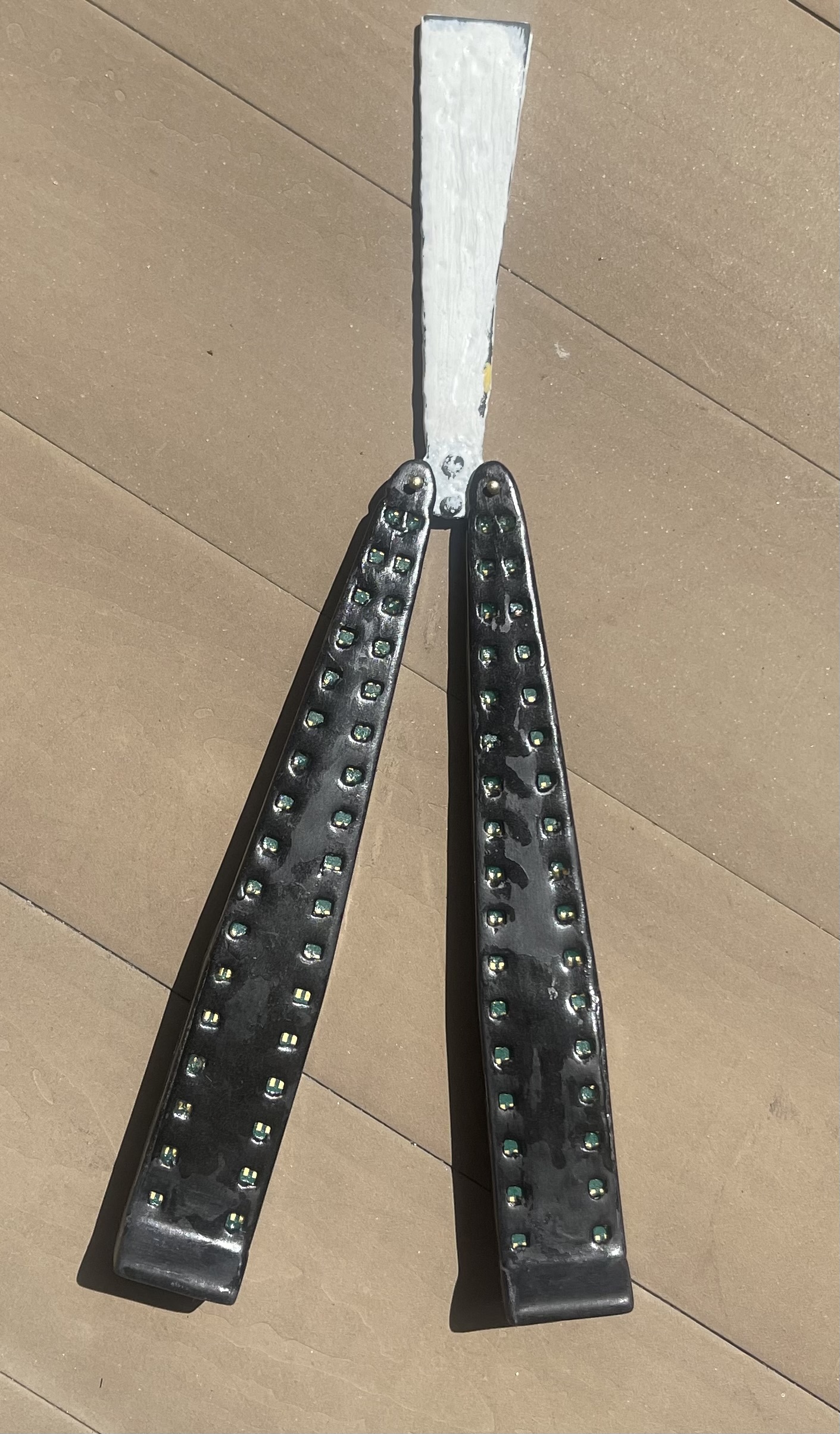
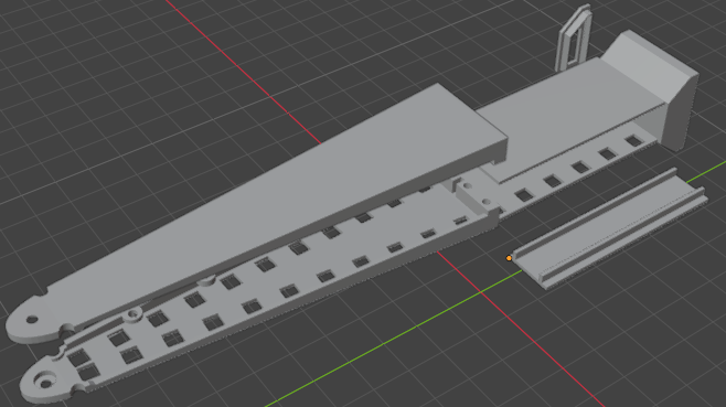
The handles are nylon carbon fiber shells that function solely as enclosures for the electronics payload. They contain no locking mechanisms and no load bearing hardware beyond the pivot pins. The two handles carry different components, arranged at mirrored positions within each shell.
4.1 Handle A (controller)
One 1,000 mAh lithium polymer cell, one Seeed XIAO ESP32 C3 microcontroller, one Bosch BMI270 inertial measurement unit, and 34 addressable LEDs (SK6812 MINI).
4.2 Handle B (sound generator and NFC)
One 1,000 mAh lithium polymer cell, one passive mechanical sound generator (3 steel ball bearings and a 6mm tube), one NFC tag (NTAG213) mounted directly beneath the sound generator, and 34 addressable LEDs (SK6812 MINI).
4.3 Sound generator
The sound generator is a short length of stainless steel tube containing a single loose steel ball bearing, capped at both ends by ball bearings. As the handle rotates during manipulation, the ball travels along the tube and produces an audible click, providing auditory feedback to the performer. It is a passive acoustic component. It contains no electronics, no wiring, and no connection to any other part of the unit. On an X-ray scan it appears as a small sealed tube with a ball inside. It can be seen below on the image on the right.
5.Materials
| Tip | Tungsten powder in a two part epoxy mix. Contains no ferrous metal. Not magnetic. |
|---|---|
| Tip finish | Cyanoacrylate seal coat, sanded, then pigmented tabletop epoxy topcoat. |
| Segmentation link | PLA plastic in three dovetail interlocked sections. TOY lettering molded in contrasting PLA. |
| Pivot pins | Solid brass, 1.5 mm diameter. |
| Handles | Nylon carbon fiber assembled via press pins, heat welded together, sanded and finished with CA glue then polyurethane and finally the maintenance wax. |
| Battery closure | Sealed with CA glue and polyurethane and maintenance wax. |
| Handle A electronics | Seeed XIAO ESP32 C3 microcontroller, Bosch BMI270 IMU, SK6812 MINI LEDs. |
| Handle B electronics | 6mm stainless steel tube sound generator with 2 6mm ball bearings on either end of the tube with a loose 5mm ball bearing inside the tube, an NFC tag, and SK6812 MINI LEDs. |
| Power | Two 1,000 mAh lithium polymer cells (3.7 V), one per handle. |
6.Air travel compliance
6.1 Transport
The product was designed to be transported in checked baggage. The integrated lithium polymer cells are well below the FAA watt hour threshold for installed batteries in checked baggage.
= 2 × 1.0 Ah × 3.7 V
= 7.4 Wh total
FAA Regulation (for installed batteries) Up to 100 Wh per battery · permitted checked or cabin
100 to 160 Wh · airline approval required
Over 160 Wh · prohibited
7.4 Wh is approximately 7 percent of the 100 Wh installed battery limit. Neither the aditional approval or prohibition thresholds apply to this unit.
6.2 Battery installation
The cells are not designed to be user removable. Each cell is retained inside its handle enclosure using cyanoacrylate adhesive, a polyurethane coating, and maintenance wax applied over the joint. The closure could be defeated with tools if someone made the effort, but it is not accessible through normal handling of the product. This classifies the cells as installed batteries under FAA guidance.